-
07 Building Webster’s Lab V2 – Create vSphere Networking and Network Storage
[Updated 8-Nov-2021]
Before creating a vSphere Distributed Switch (vDS), we need to create a Datacenter.
Verify you are connected and logged in to the vCenter console.
Click Menu and click VMs and Templates, as shown in Figure 1.
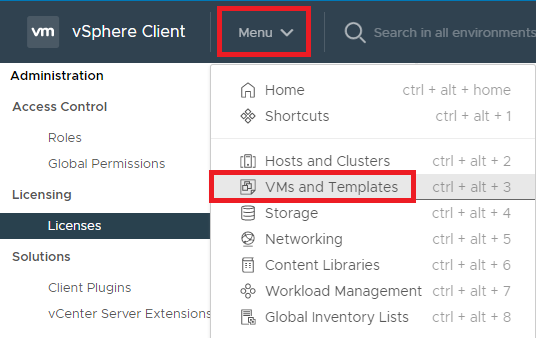
Figure 1 Right-click the vCenter VM and click New Datacenter…, as shown in Figure 2.
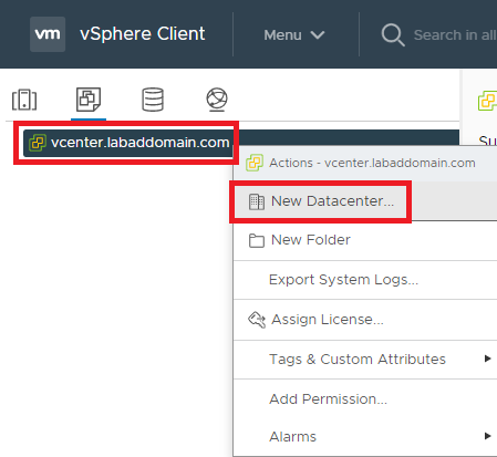
Figure 2 Enter a Name for the Datacenter and click OK, as shown in Figure 3.
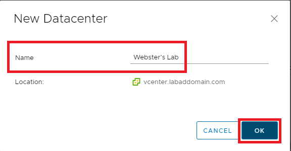
Figure 3 The new Datacenter is shown in the vCenter console, as shown in Figure 4.
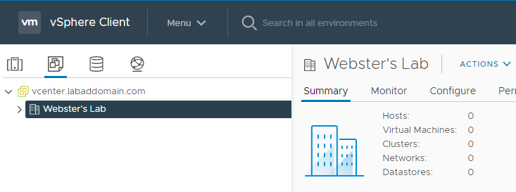
Figure 4 Now the hosts are added to vCenter.
Click the Hosts and Clusters node in vCenter, as shown in Figure 5.
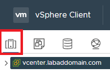
Figure 5 Expand the Hosts and Clusters node, right-click the Datacenter and click Add Host…, as shown in Figure 6.
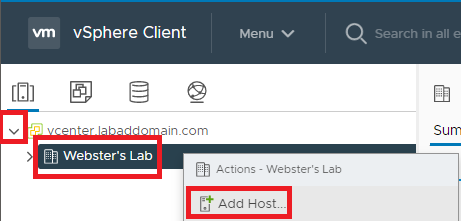
Figure 6 Enter the Hostname or IP address or the host to add and click Next, as shown in Figure 7.
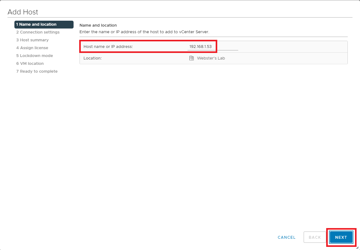
Figure 7 Enter a User name and Password to connect to the ESXi host and click Next, as shown in Figure 8.
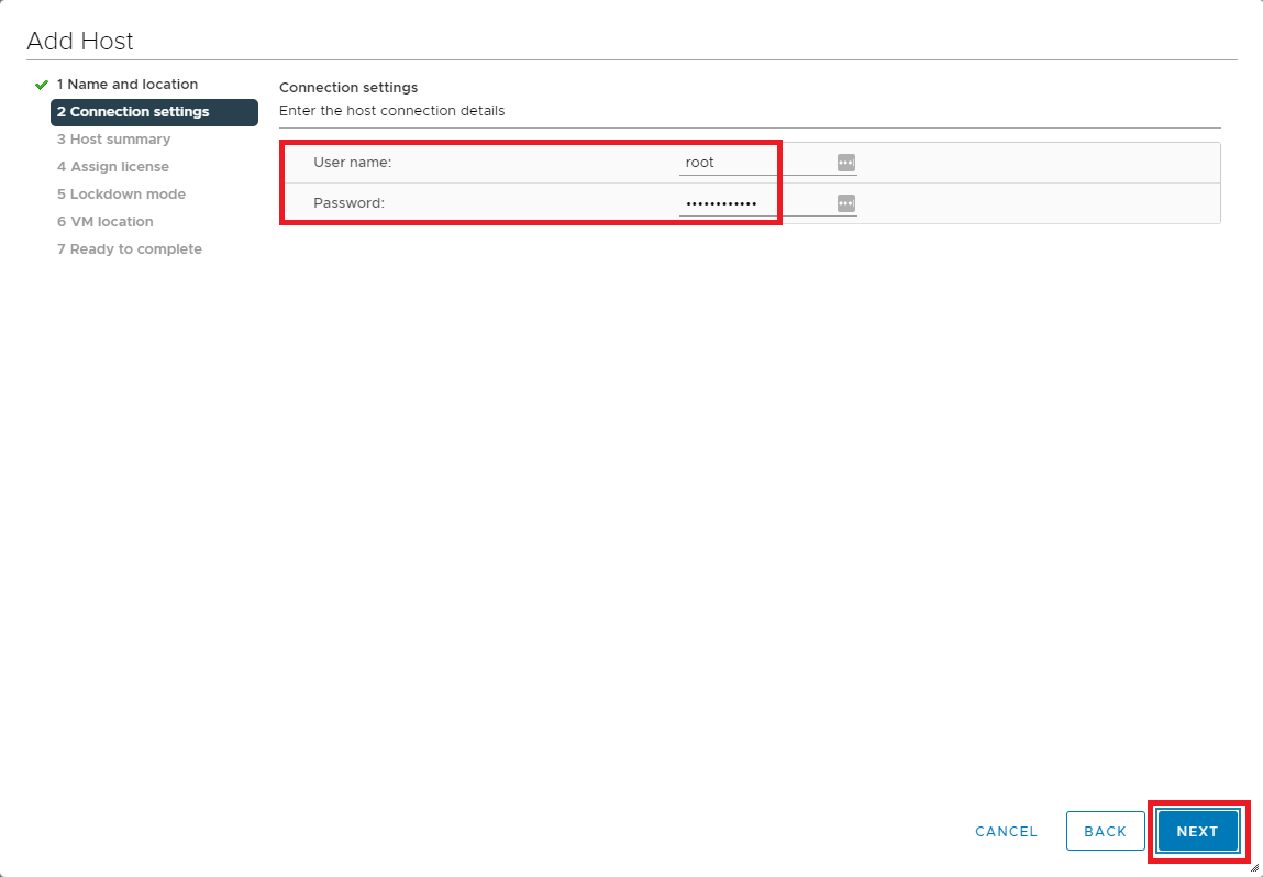
Figure 8 Because of the host’s self-signed certificate, click Yes on the Security Alert popup, as shown in Figure 9.
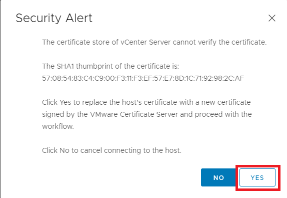
Figure 9 Click Next, as shown in Figure 10.
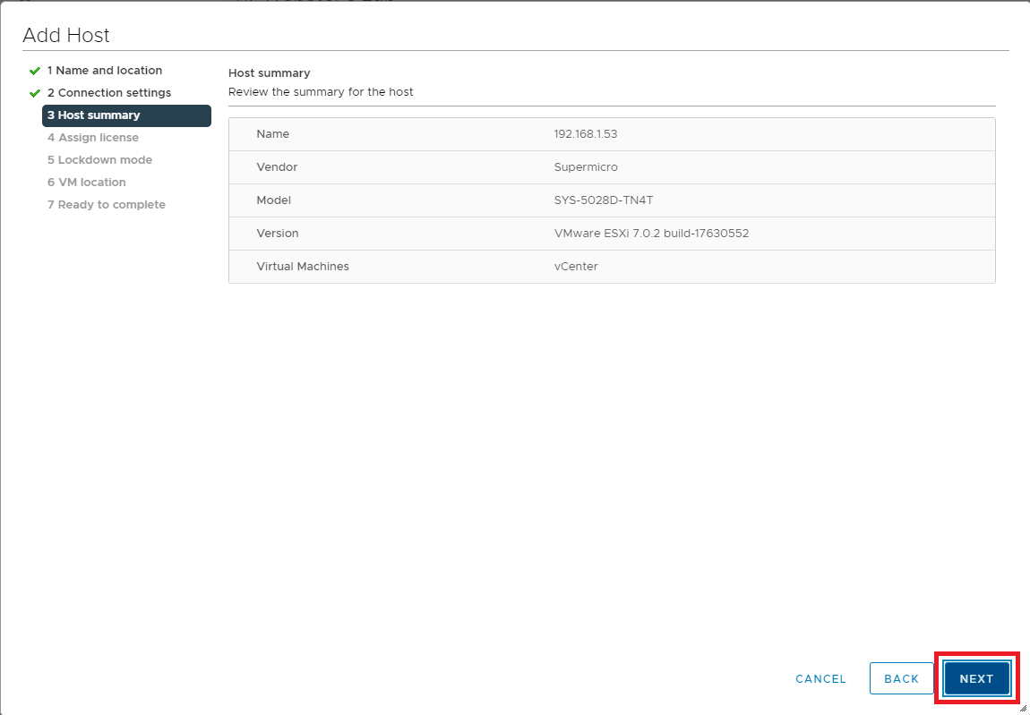
Figure 10 Select the license to assign the host and click Next, as shown in Figure 11.
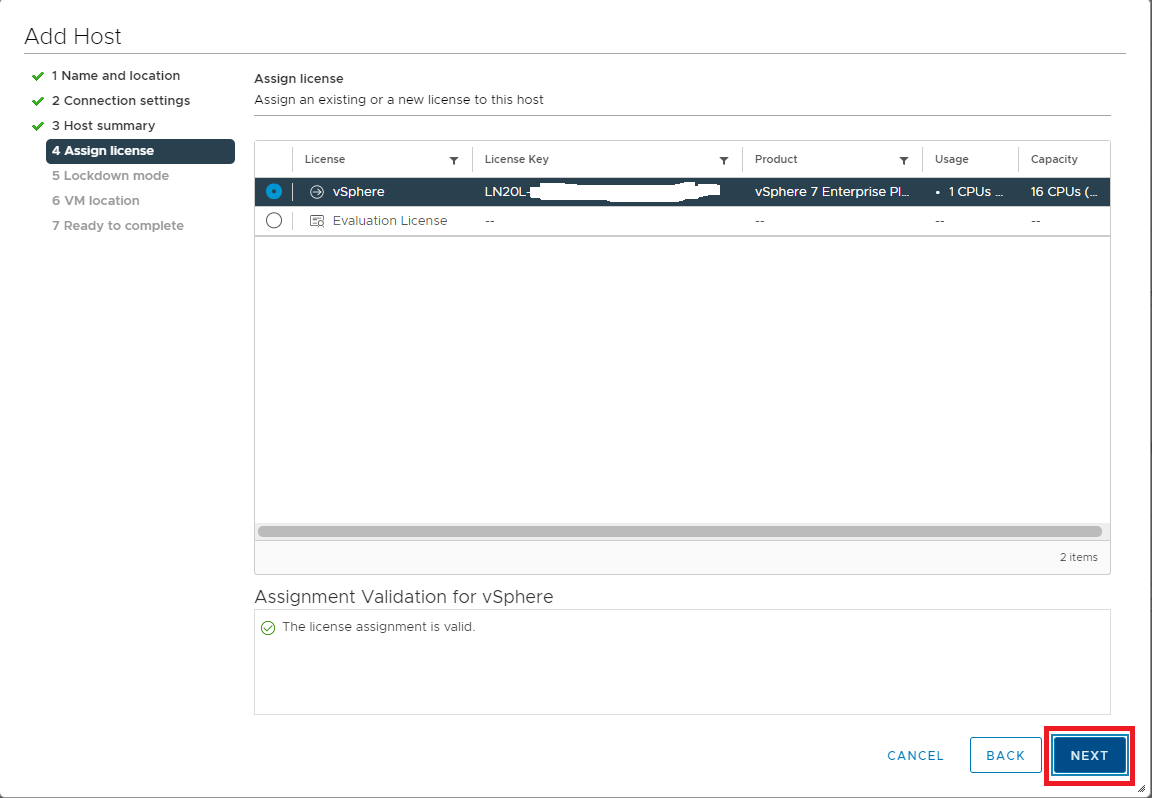
Figure 11 Selected the preferred Lockdown mode and click Next, as shown in Figure 12.
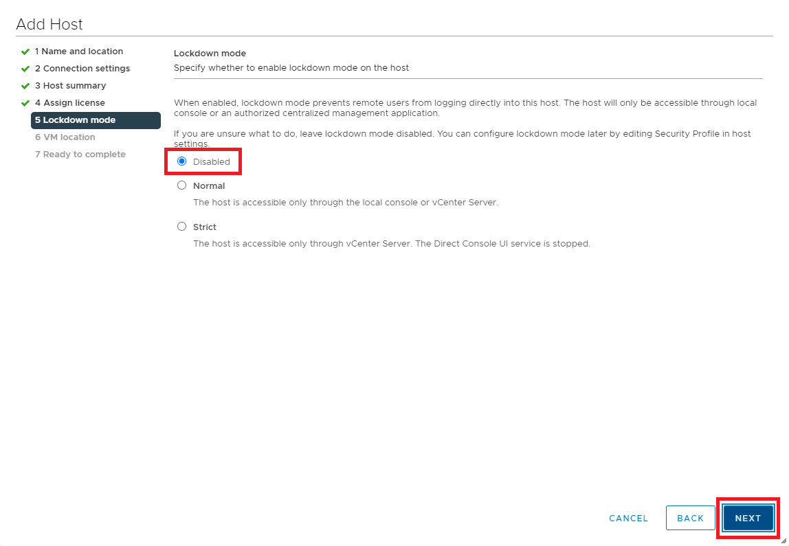
Figure 12 Click Next, as shown in Figure 13.
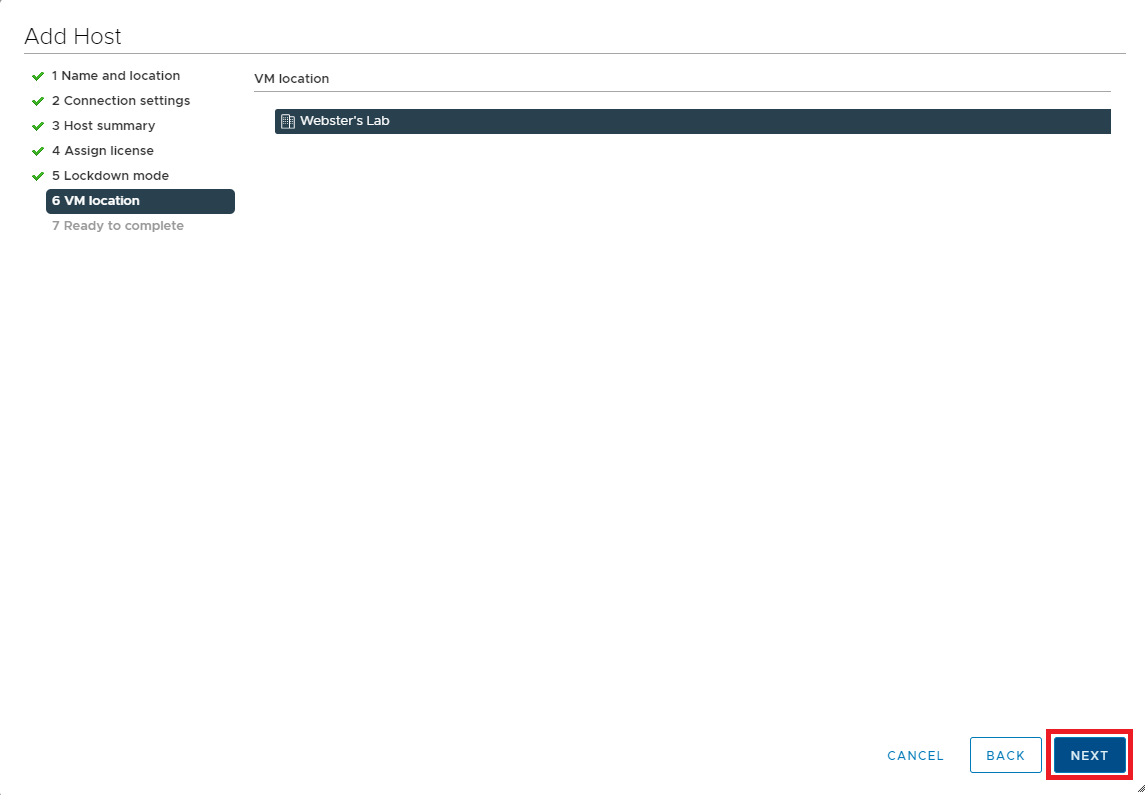
Figure 13 If all the information is correct, click Finish, as shown in Figure 14. If the information is not correct, click Back, correct the information, and then continue.
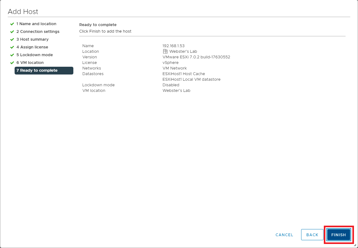
Figure 14 Repeat the steps outlined in Figures 6 through 14 to add additional hosts to vCenter.
Next is creating a Cluster.
Once you add all hosts to vCenter, right-click the Datacenter and click New Cluster…, as shown in Figure 15.
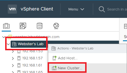
Figure 15 Enter a Name for the cluster and click OK, as shown in Figure 16.
Note: For my lab, at this time, I do not use the “single image” host and cluster lifecycle. Please read About Managing Host and Cluster Lifecycle if you want more information on this new vCenter 7 feature.
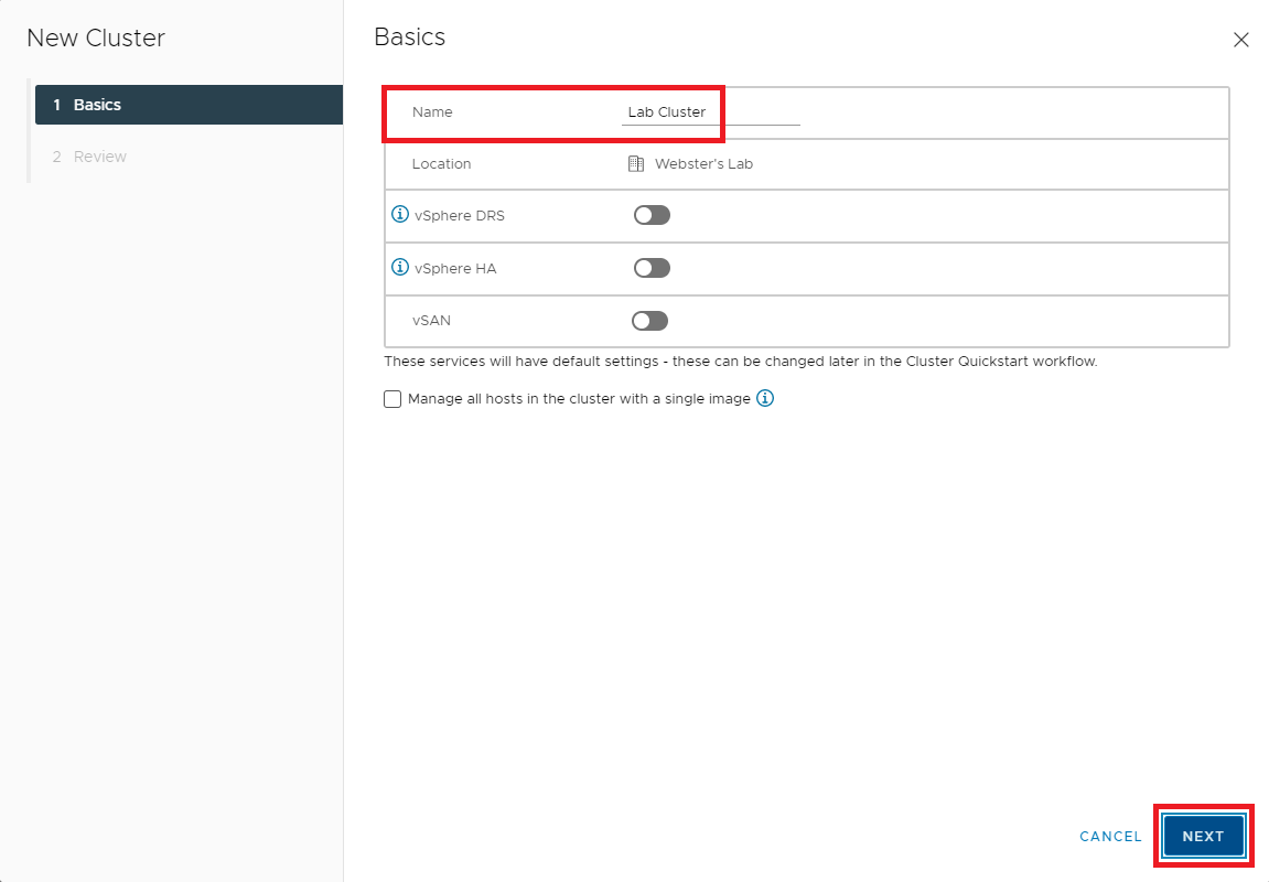
Figure 16 Click Finish, as shown in Figure 17.
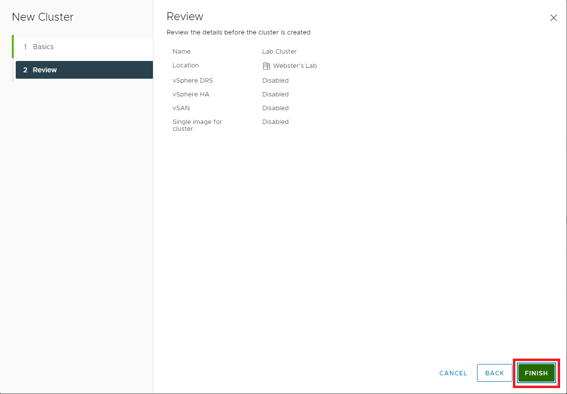
Figure 17 In the left pane, click the new cluster as shown in Figure 18.
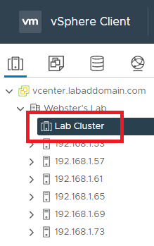
Figure 18 In Cluster quickstart, in the right pane, click the Edit button in the Cluster basics box, as shown in Figure 19.
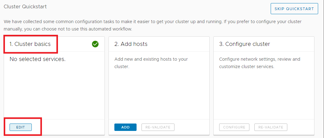
Figure 19 Enable vSphere DRS (to allow the automatic creation of vMotion later) and click OK, as shown in Figure 20.
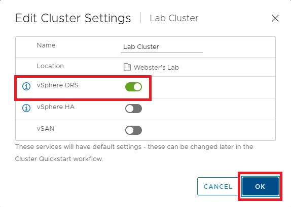
Figure 20 In Cluster quickstart, click the Add button in the Add hosts box in the right pane, as shown in Figure 21.
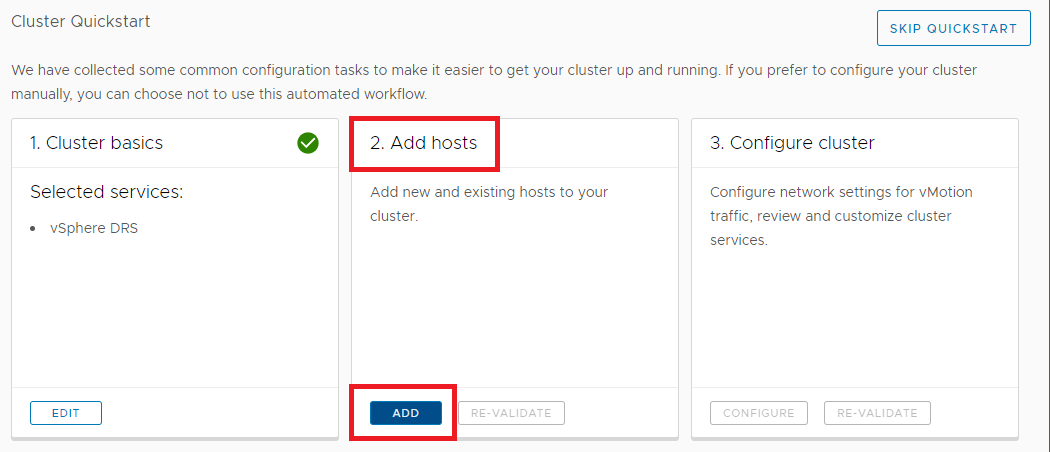
Figure 21 Select Existing hosts, select the hosts to add and click Next, as shown in Figure 22.
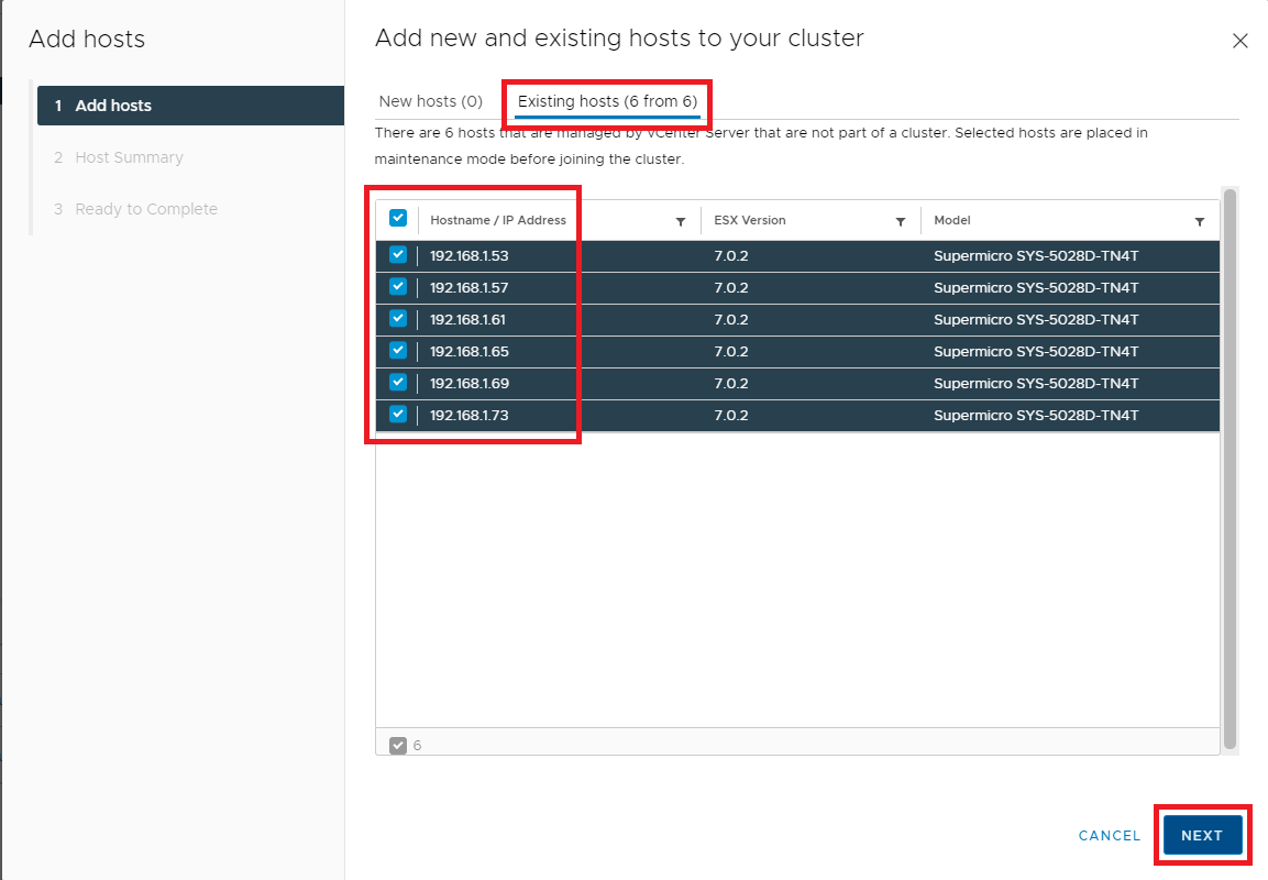
Figure 22 Click Next, as shown in Figure 23.
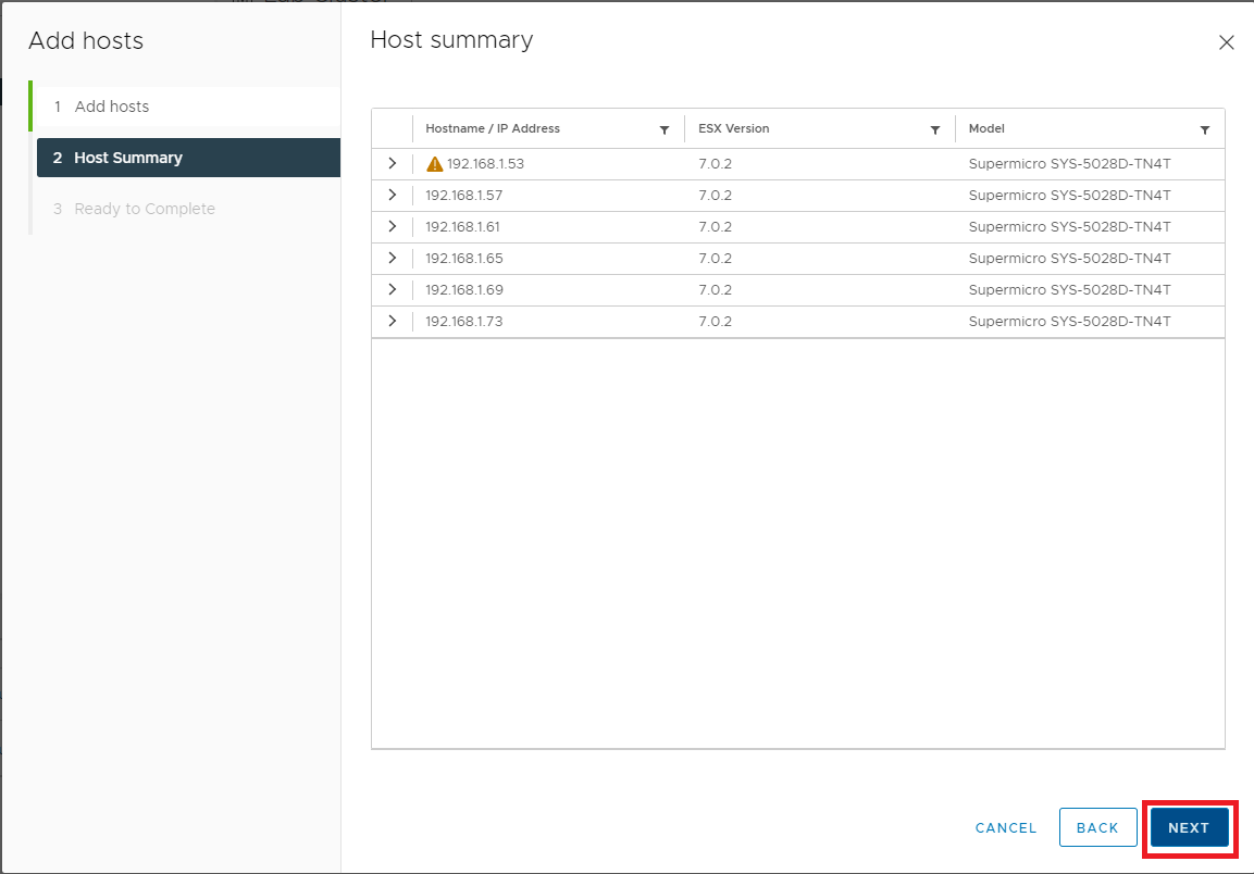
Figure 23 If all the information is correct, click Finish, as shown in Figure 24. If the information is not correct, click Back, correct the information, and then continue.
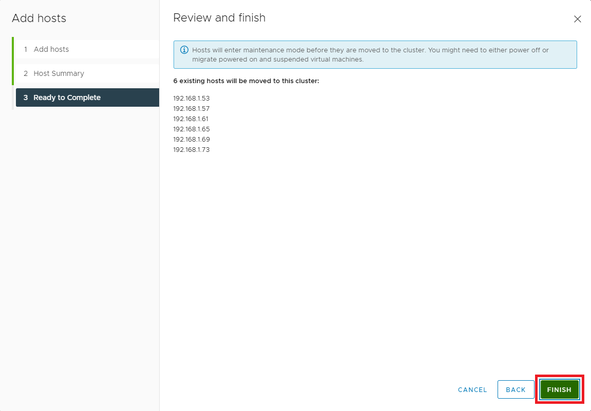
Figure 24 In the vCenter console, you can see the hosts added to the cluster, as shown in Figure 25.
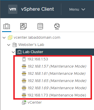
Figure 25 Now on to the fun stuff: Networking.
I tried to come up with my explanation of port groups, virtual switches, physical NICs, VMkernel NICs, TCP/IP stacks, uplinks, and other items but found VMware already had something even I could understand.
I found the following information in the vSphere Networking Concepts Overview documentation, Copyright VMware, Inc., available at https://docs.vmware.com/en/VMware-vSphere/7.0/com.vmware.vsphere.networking.doc/GUID-2B11DBB8-CB3C-4AFF-8885-EFEA0FC562F4.html.
Networking Concepts Overview
A few concepts are essential for a thorough understanding of virtual networking. If you are new to ESXi, it is helpful to review these concepts.
Physical Network
A network of physical machines that are connected so that they can send data to and receive data from each other. VMware ESXi runs on a physical machine.
Virtual Network
A network of virtual machines running on a physical machine that are connected logically to each other so that they can send data to and receive data from each other. Virtual machines can be connected to the virtual networks that you create when you add a network.
Opaque Network
An opaque network is a network created and managed by a separate entity outside of vSphere. For example, logical networks that are created and managed by VMware NSX ® appear in vCenter Server as opaque networks of the type nsx.LogicalSwitch. You can choose an opaque network as the backing for a VM network adapter. To manage an opaque network, use the management tools associated with the opaque network, such as VMware NSX ® Manager or the VMware NSX API management tools.
Note: With NSX-T 3.0, it is now possible to run NSX-T directly on vSphere Distributed Switch (vDS) version 7.0 or later. Such networks are not opaque and are identified as NSX logical segments running on vDS 7.0. For more information, see Knowledge Base article KB #79872.
Physical Ethernet Switch
A physical ethernet switch manages network traffic between machines on the physical network. A switch has multiple ports, each of which can be connected to a single machine or another switch on the network. Each port can be configured to behave in certain ways depending on the needs of the machine connected to it. The switch learns which hosts are connected to which of its ports and uses that information to forward traffic to the correct physical machines. Switches are the core of a physical network. Multiple switches can be connected together to form larger networks.
vSphere Standard Switch
It works much like a physical Ethernet switch. It detects which virtual machines are logically connected to each of its virtual ports and uses that information to forward traffic to the correct virtual machines. A vSphere standard switch can be connected to physical switches by using physical Ethernet adapters, also referred to as uplink adapters, to join virtual networks with physical networks. This type of connection is similar to connecting physical switches together to create a larger network. Even though a vSphere standard switch works much like a physical switch, it does not have some of the advanced functionality of a physical switch.
vSphere Distributed Switch
A vSphere distributed switch acts as a single switch across all associated hosts in a data center to provide centralized provisioning, administration, and monitoring of virtual networks. You configure a vSphere distributed switch on the vCenter Server system and the configuration is propagated to all hosts that are associated with the switch. This lets virtual machines maintain consistent network configuration as they migrate across multiple hosts.
Host Proxy Switch
A hidden standard switch that resides on every host that is associated with a vSphere distributed switch. The host proxy switch replicates the networking configuration set on the vSphere distributed switch to the particular host.
Standard Port Group
Network services connect to standard switches through port groups. Port groups define how a connection is made through the switch to the network. Typically, a single standard switch is associated with one or more port groups. A port group specifies port configuration options such as bandwidth limitations and VLAN tagging policies for each member port.
Distributed Port
A port on a vSphere distributed switch that connects to a host’s VMkernel or to a virtual machine’s network adapter.
Distributed Port Group
A port group associated with a vSphere distributed switch that specifies port configuration options for each member port. Distributed port groups define how a connection is made through the vSphere distributed switch to the network.
NSX Distributed Port Group
A port group associated with a vSphere distributed switch that specifies port configuration options for each member port. To distinguish between vSphere distributed port groups and NSX port groups, in the vSphere Client the NSX virtual distributed switch, and its associated port group is identified with the icon. NSX appears as an opaque network in vCenter Server, and you cannot configure NSX settings in vCenter Server. The NSX settings displayed are read-only. You configure NSX distributed port groups using VMware NSX ® Manager or the VMware NSX API management tools.
NIC Teaming
NIC teaming occurs when multiple uplink adapters are associated with a single switch to form a team. A team can either share a load of traffic between physical and virtual networks among some or all of its members or provide passive failover in the event of a hardware failure or a network outage.
VLAN
VLAN enables a single physical LAN segment to be further segmented so that groups of ports are isolated from one another as if they were on physically different segments. The standard is 802.1Q.
VMkernel TCP/IP Networking Layer
The VMkernel networking layer provides connectivity to hosts and handles the standard infrastructure traffic of vSphere vMotion, IP storage, Fault Tolerance, and vSAN.
IP Storage
Any form of storage that uses TCP/IP network communication as its foundation. iSCSI and NFS can be used as virtual machine datastores and for direct mounting of .ISO files, which are presented as CD-ROMs to virtual machines.
TCP Segmentation Offload
TCP Segmentation Offload, TSO, allows a TCP/IP stack to emit large frames (up to 64KB) even though the maximum transmission unit (MTU) of the interface is smaller. The network adapter then separates the large frame into MTU-sized frames and prepends an adjusted copy of the initial TCP/IP headers.

VMware Standard Switch 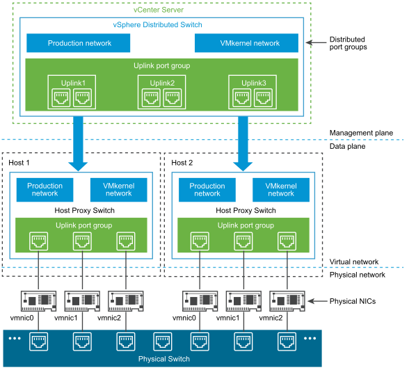
VMware Distributed Switch My TinkerTry server has two 1Gb NICs and two 10Gb NICs. I want to use all four NICs. Two vDSes are required; one for the two 1Gb NICs and one for the two 10Gb NICs.
In Cluster quickstart, click the Configure button in the Configure cluster box as shown in Figure 26.
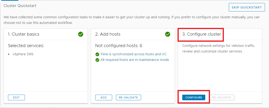
Figure 26 I want to create a vDS for each pair of NICs and name them to associate them with the NIC port speed.
Using the scrollbar, scroll down so you can see the Distributed switches and Physical adapters on one screen.
As shown in Figures 27 and 28:
- From the Number of distributed switches dropdown, select 2
- Give each distributed switch a Name
- Select which Port group to use for vMotion
- Select the Physical adapters to match to each distributed switch
- When complete, click
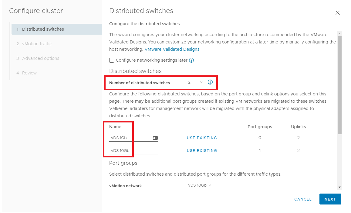
Figure 27 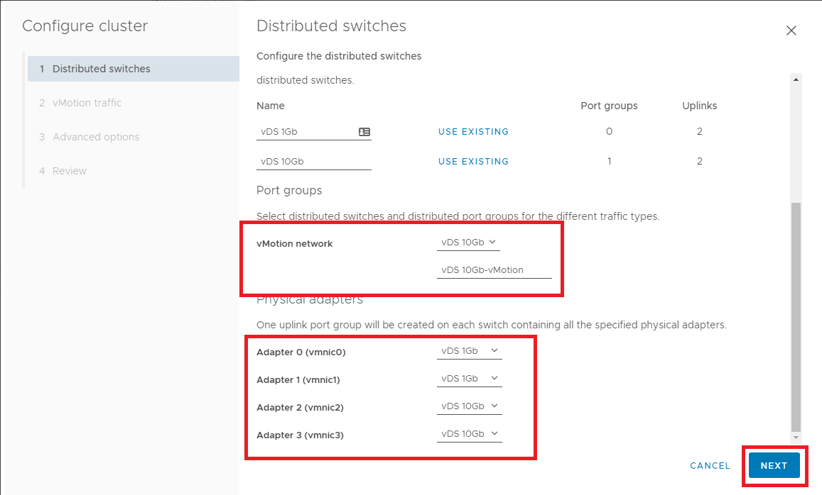
Figure 28 Change the IP Type to Static IPs, enter the IP information for vMotion as shown in Figure 29, and click Next.
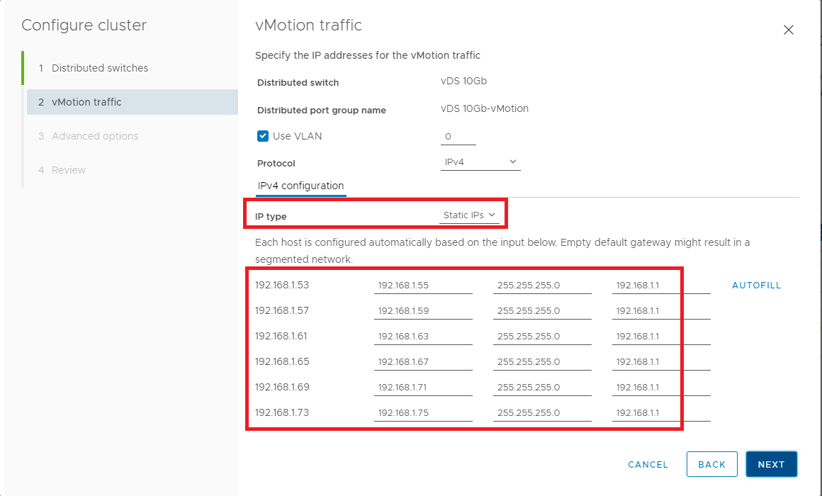
Figure 29 Select the appropriate options and click Next, as shown in Figure 30.
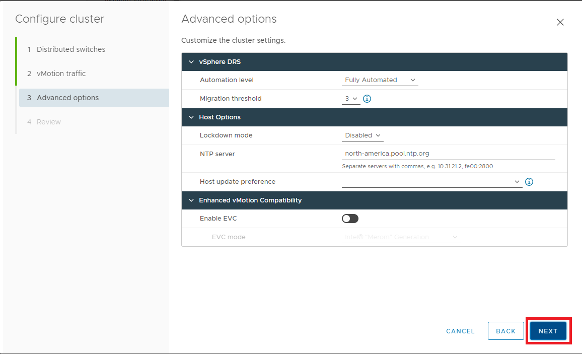
Figure 30 If all the information is correct, click Finish, as shown in Figure 31. If the information is not correct, click Back, correct the settings, and then continue.
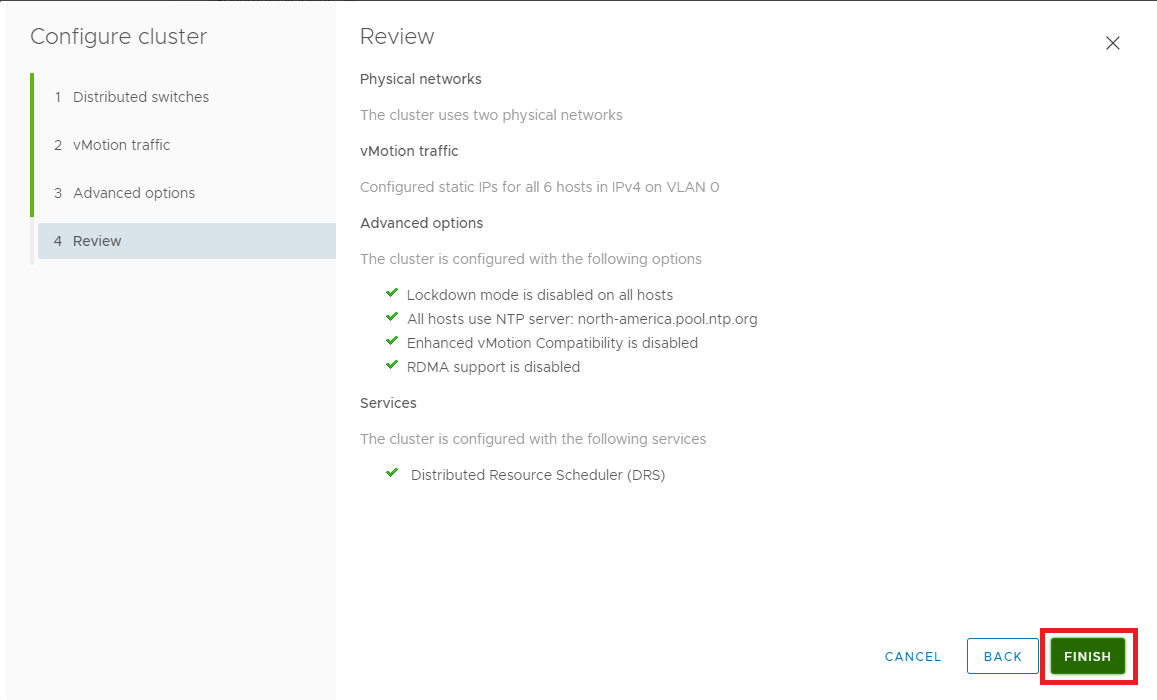
Figure 31 Click the Networking icon, expand the cluster, and each vDS, as shown in Figure 32.
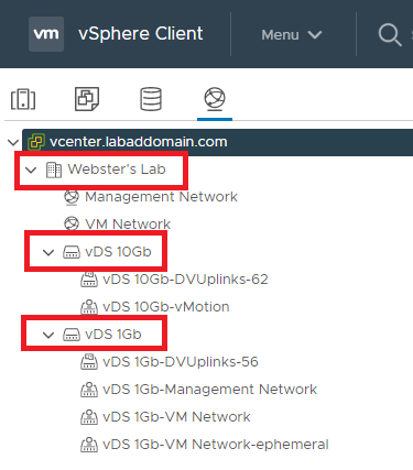
Figure 32 Verify that the vDS 10Gb switch has an MTU of 9000.
Right-click vDS 10Gb, click Settings and click Edit Settings…, as shown in Figure 33.
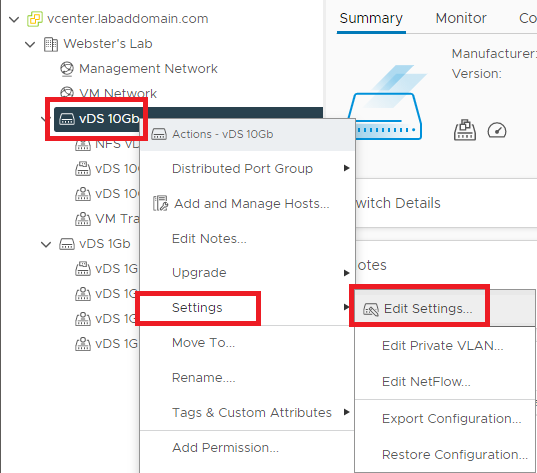
Figure 33 Click Advanced and verify that MTU (Bytes) equals 9000. If the value is not 9000, change it to 9000 and click OK, as shown in Figure 34.
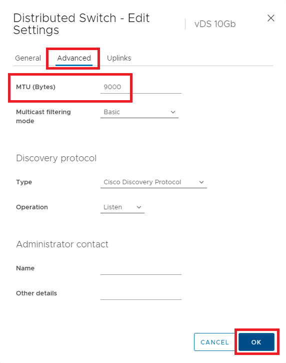
Figure 34 I plan to use the vDS 10Gb switch for VM, vMotion, and Storage traffic. To accomplish that, two different Port Groups are required. We created the vMotion Port Group earlier in Figure 29.
Right-click the vDS 10Gb switch, select Distributed Port Group, select New Distributed Port Group…, as shown in Figure 35.
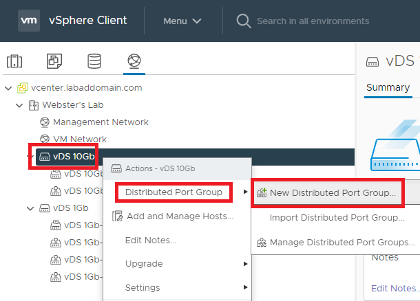
Figure 35 The Name for this port group is VM Traffic vDS 10Gb. Click Next, as shown in Figure 36.
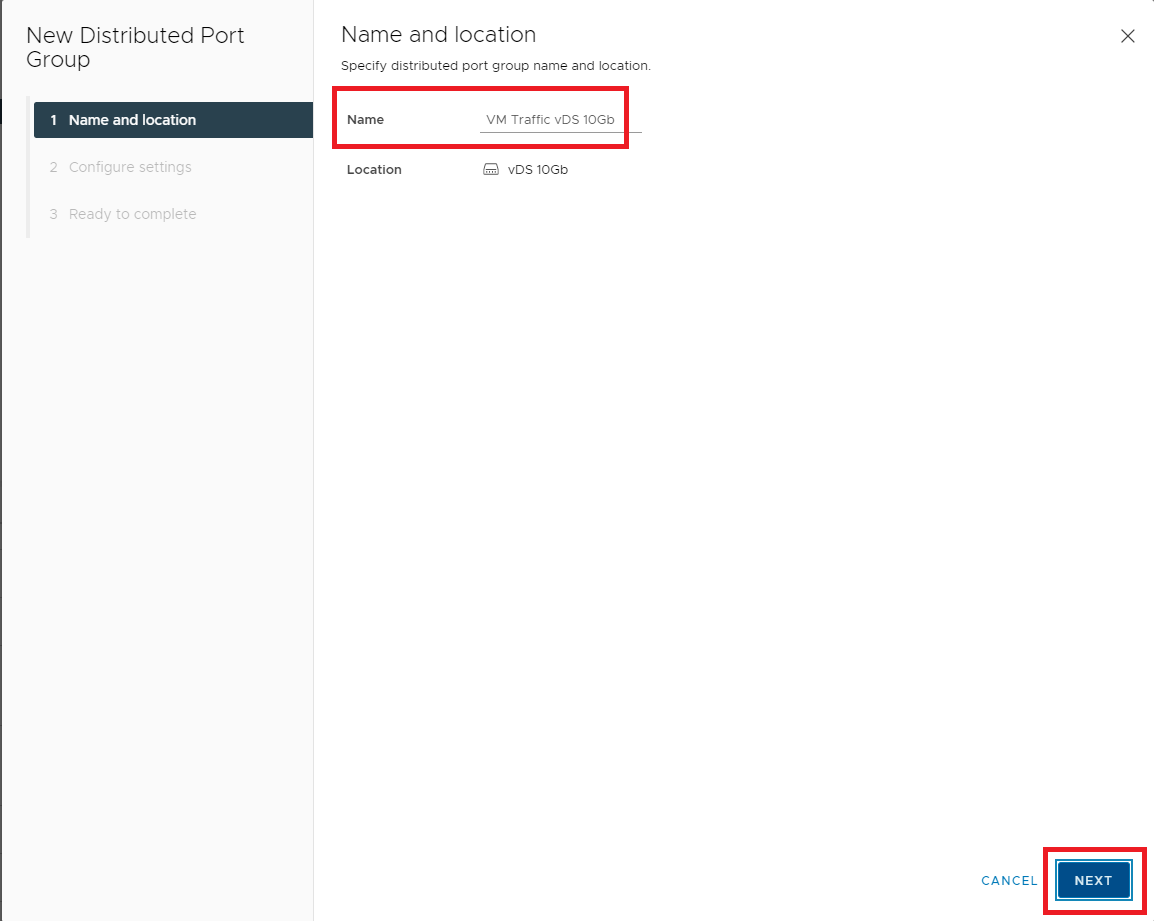
Figure 36 For my lab, the default general properties are suitable. Click Next, as shown in Figure 37.
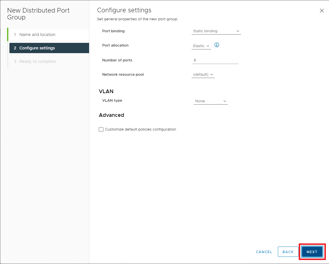
Figure 37 If all the information is correct, click Finish, as shown in Figure 38. If the information is not correct, click Back, correct the information, and then continue.
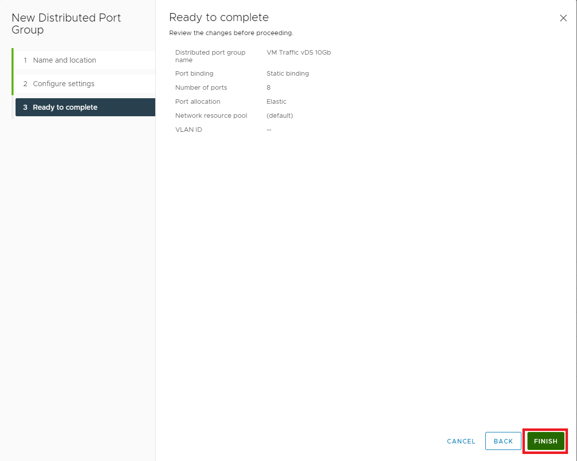
Figure 38 Repeat these steps to create a different port group with the Name: NFS vDS 10Gb.
When complete, the Distributed Port Groups should look like Figure 39.
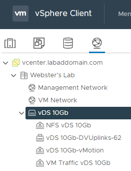
Figure 39 vMotion and NFS storage require VMkernel NICs. The vMotion VMkernel NIC was created earlier as part of the vDS creation wizard (Figure 29).
Right-click the NFS vDS 10Gb distributed port group and click Add VMkernel Adapters…, as shown in Figure 40.
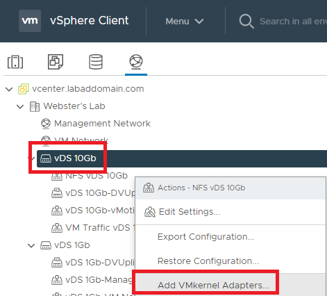
Figure 40 Click Attached hosts…, as shown in Figure 41.
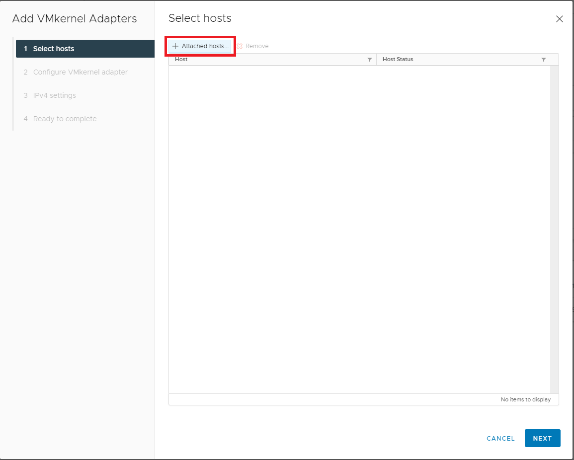
Figure 41 Select all hosts and click OK, as shown in Figure 42.
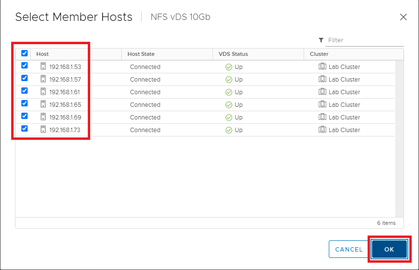
Figure 42 Click Next, as shown in Figure 43.
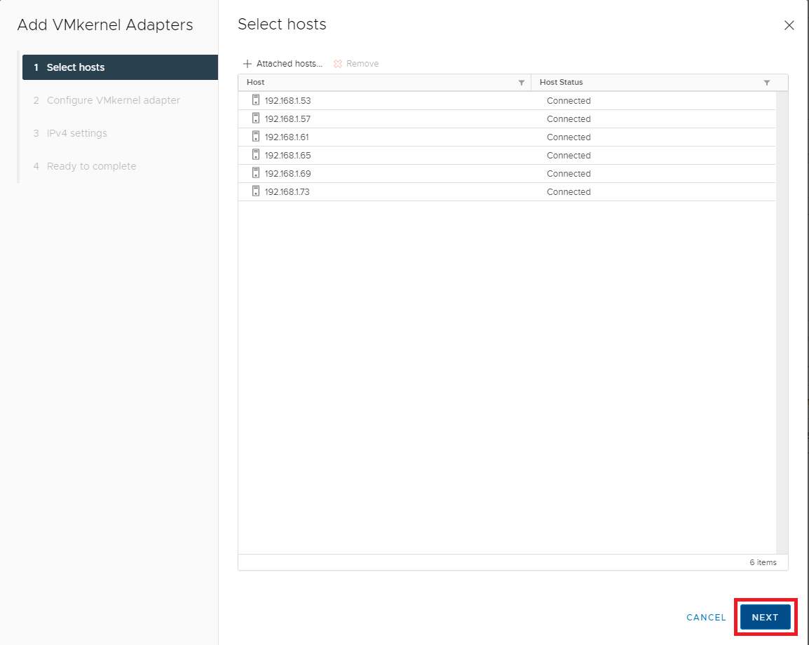
Figure 43 Enter the following information:
- MTU: Enter the MTU for your 10G switch (typically 9000)
- TCP/IP stack: select Default from the dropdown list
- Available services -> Leave all unselected
Click Next, as shown in Figure 44.
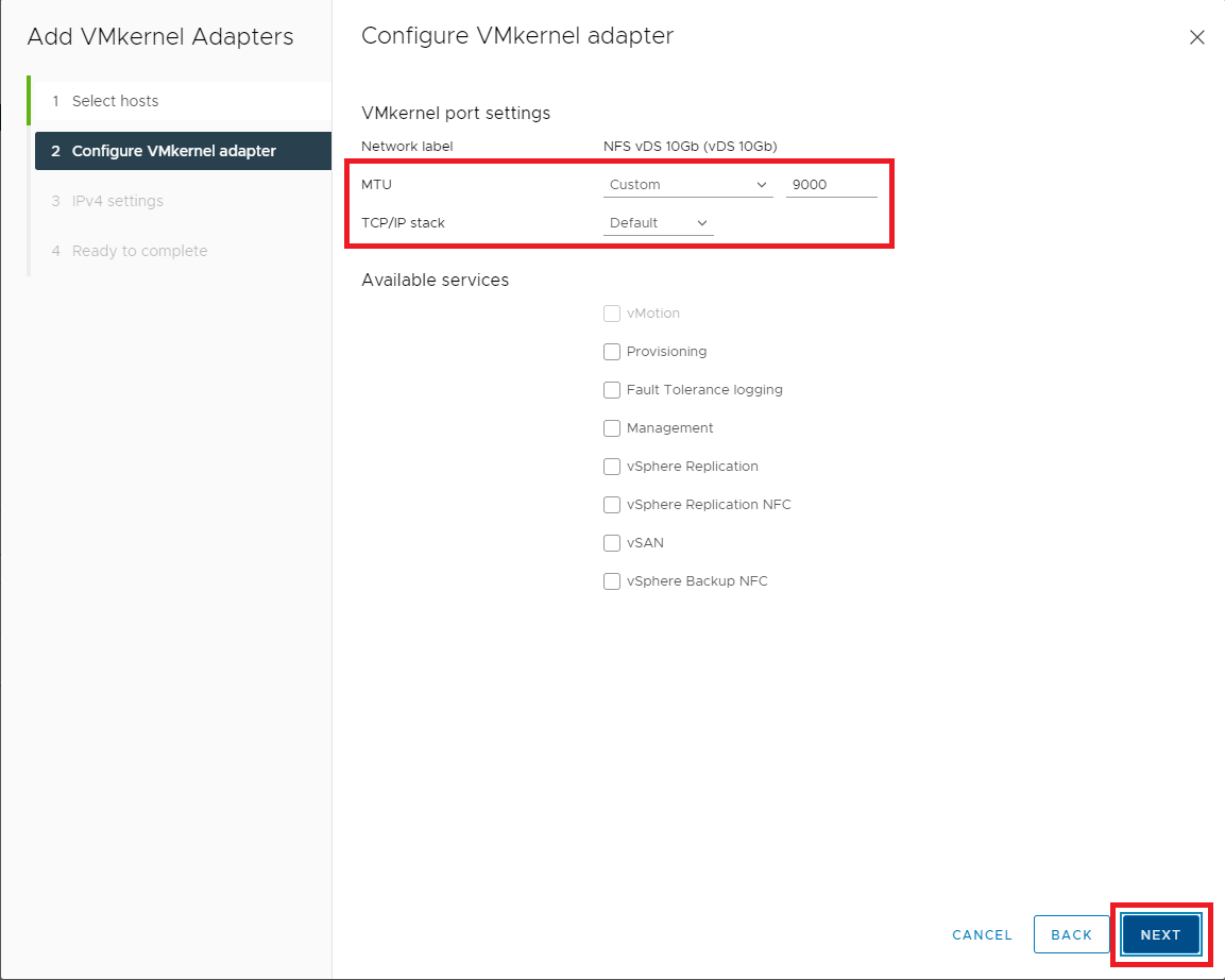
Figure 44 Select Use static IPv4 settings. For each host, enter the IP address and subnet for the NFS VMkernel and click Next, as shown in Figure 45.
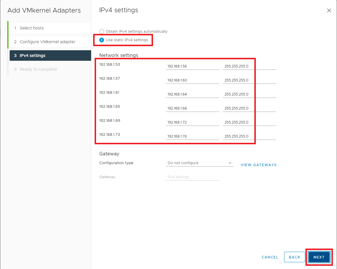
Figure 45 If all the information is correct, click Finish, as shown in Figure 46. If the information is not correct, click Back, correct the information, and then continue.
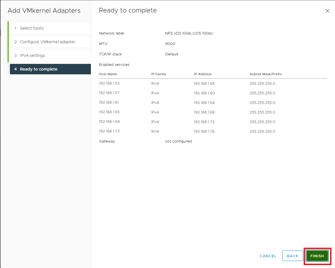
Figure 46 Now that our networking is complete let’s move on to configuring NFS Storage.
Click Storage, as shown in Figure 47.
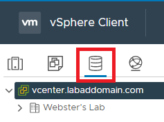
Figure 47 First up is an NFS datastore to hold VMs.
Right-click the cluster, click Storage, click New Datastore…, as shown in Figure 48.
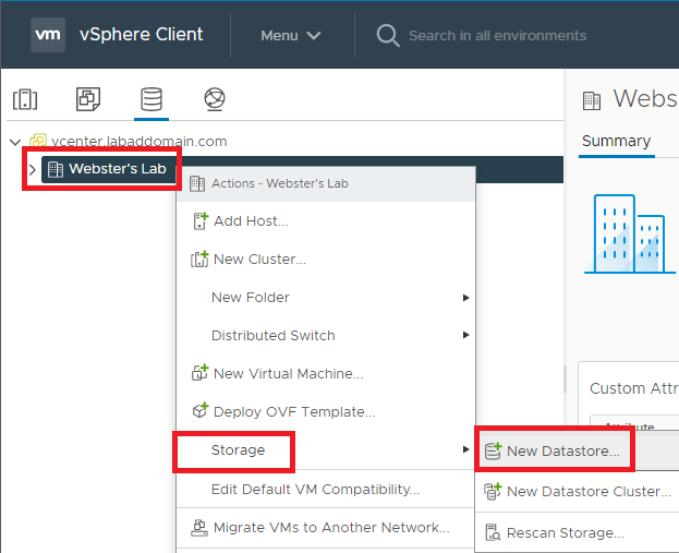
Figure 48 Select NFS and click Next, as shown in Figure 49.
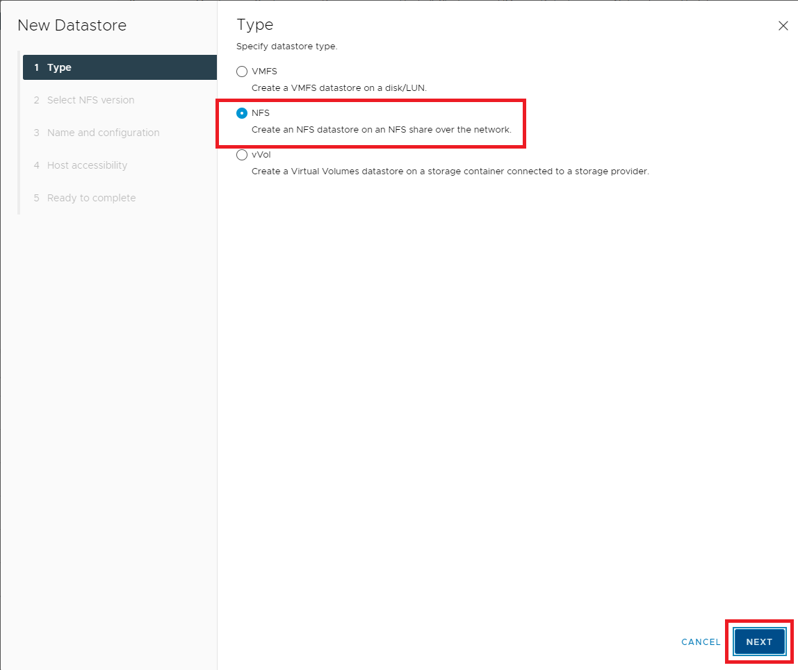
Figure 49 Select NFS 4.1 and click Next, as shown in Figure 50.
Note: VMware has an article to show the differences in the capabilities of NFS 3 and NFS 4.1. Please see NFS Protocols and ESXi.
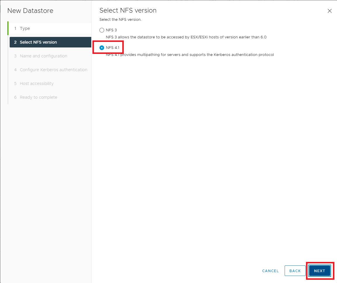
Figure 50 Enter a Datastore Name, the Folder on the NFS server, the NFS Server name or IP address, and click Add, as shown in Figure 51.
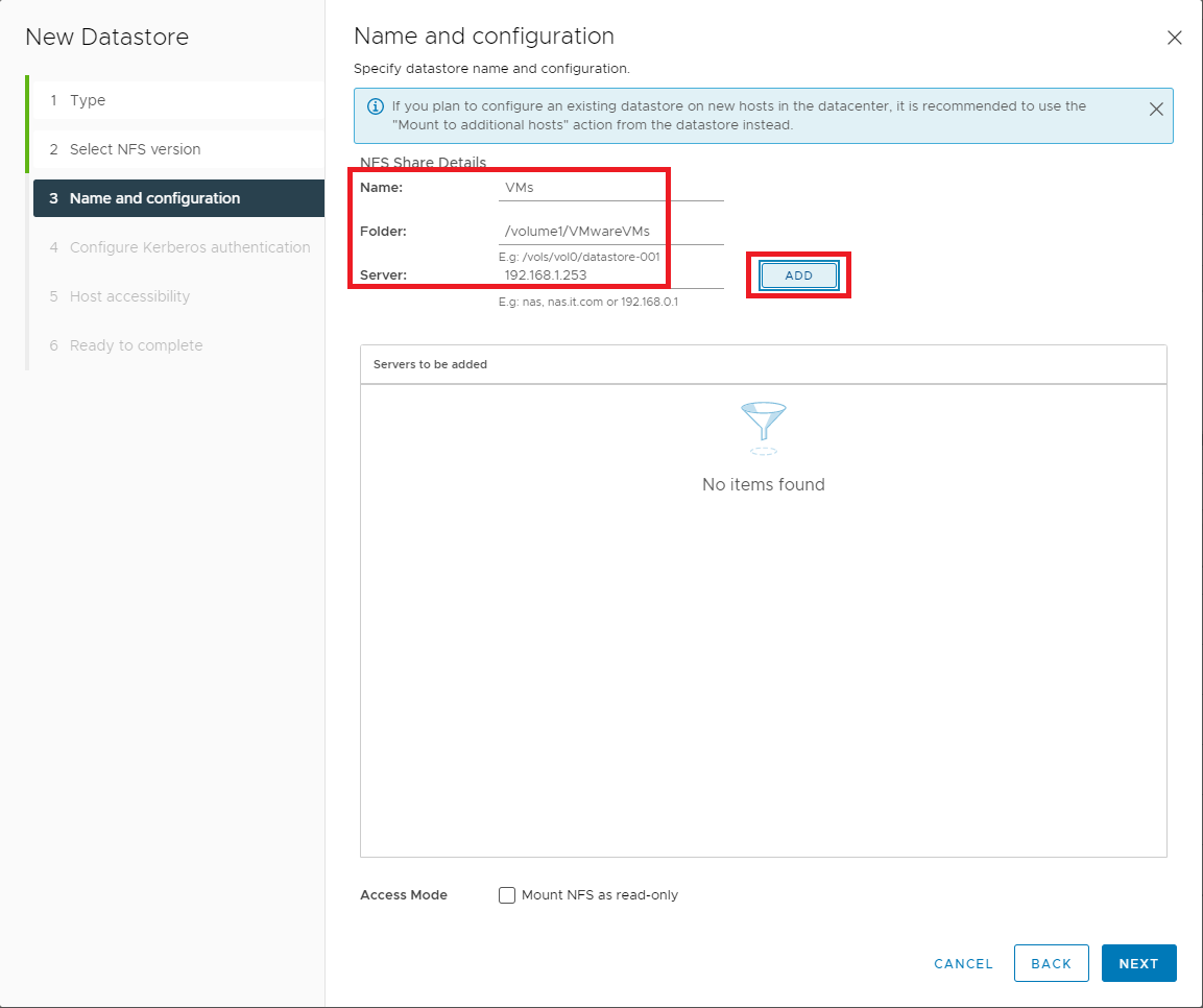
Figure 51 Click Next, as shown in Figure 52.
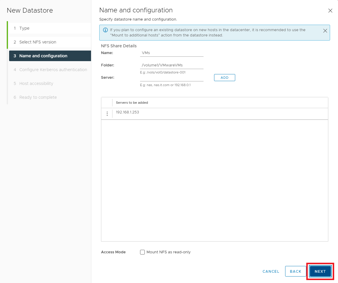
Figure 52 Select the Kerberos authentication option required for your NAS and click Next, as shown in Figure 53.
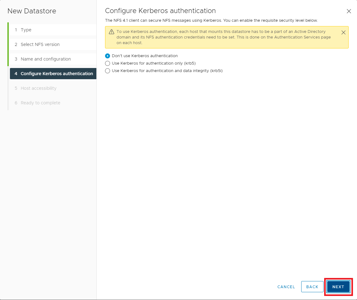
Figure 53 Select all hosts in the cluster and click Next, as shown in Figure 54.
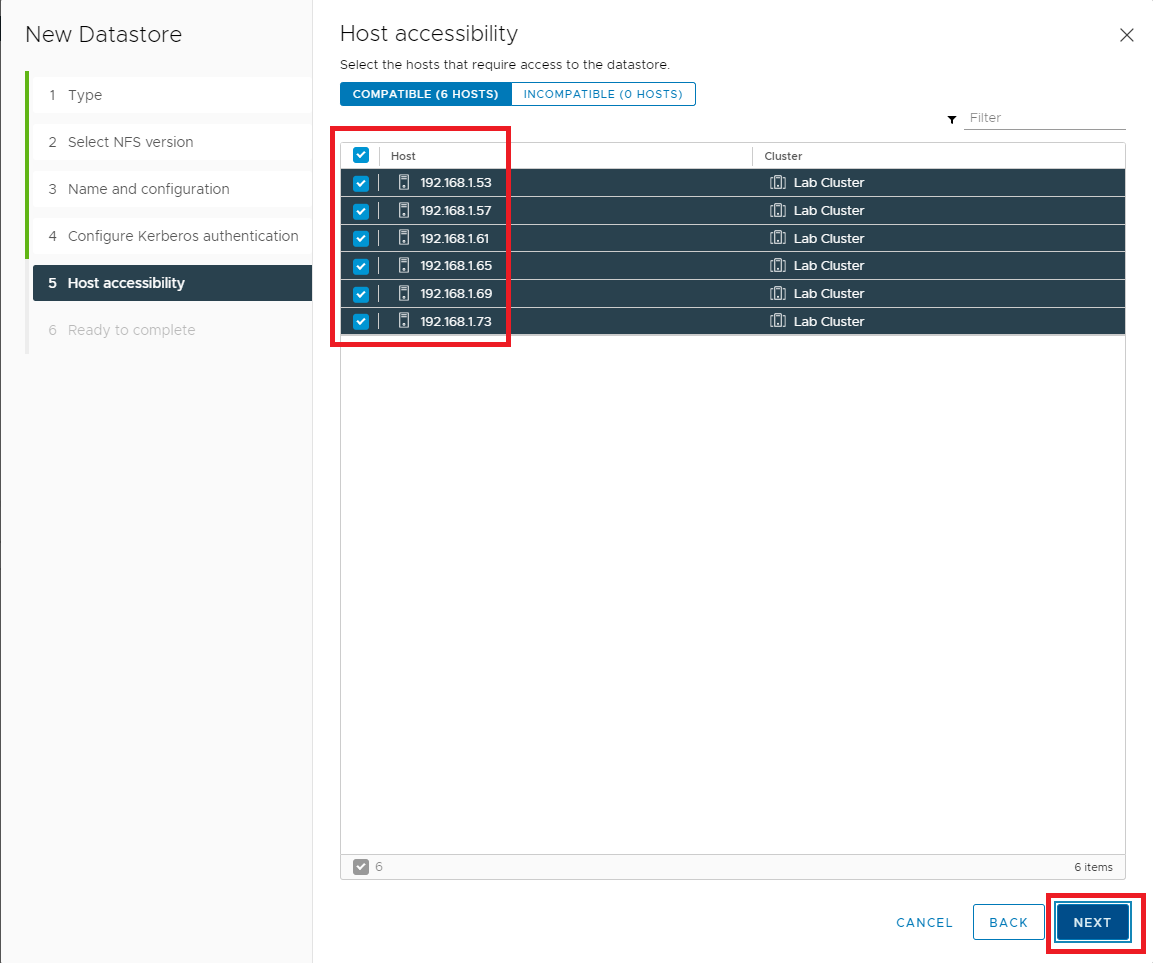
Figure 54 If all the information is correct, click Finish, as shown in Figure 55. If the information is not correct, click Back, correct the information, and then continue.
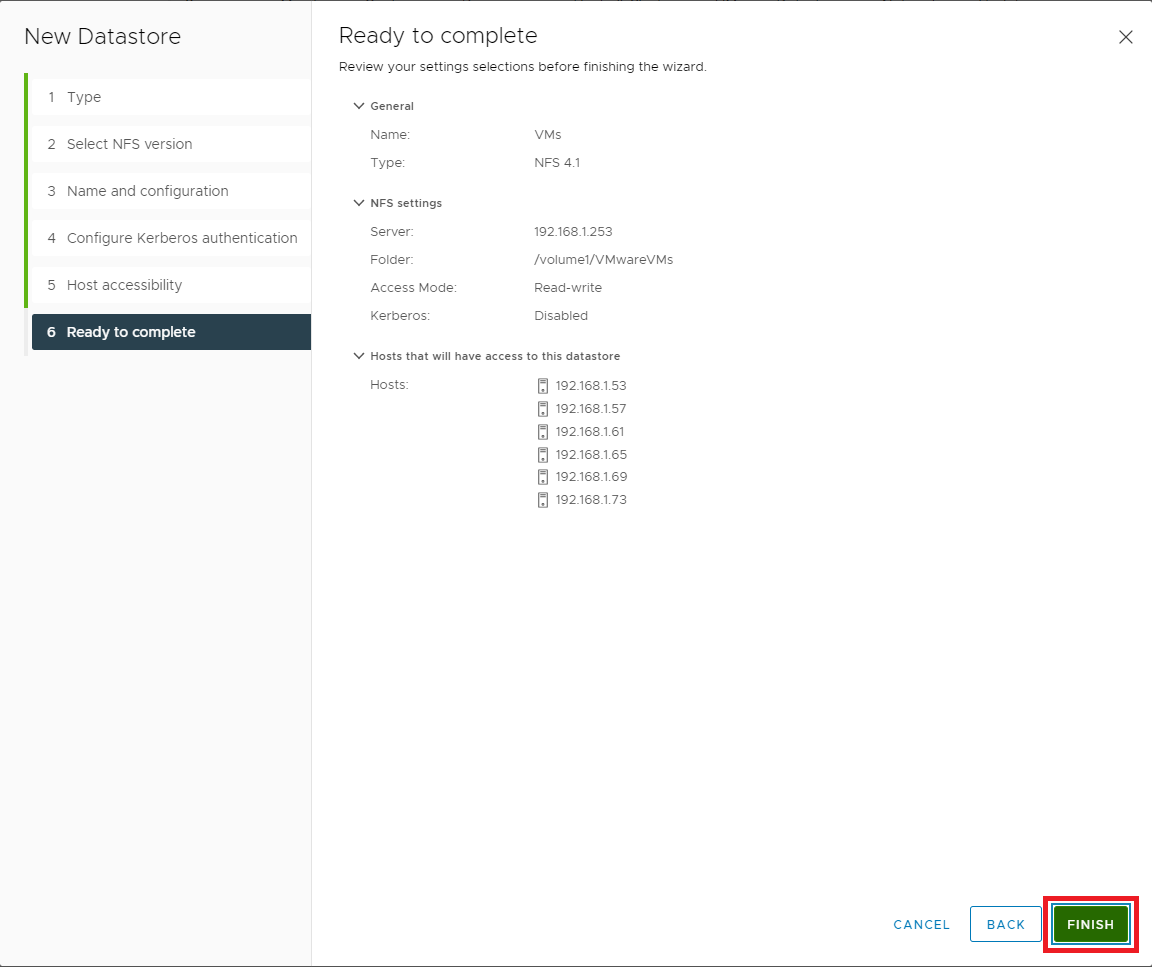
Figure 55 Next, let’s verify the VAAI configuration for the datastore. Click the VM datastore, click Configure and click Hardware Acceleration, as shown in Figure 56.
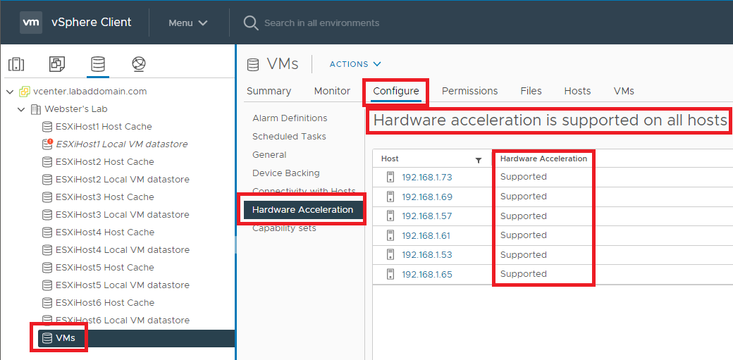
Figure 56 Repeat the steps outlined in Figures 48 through 55 to create an NFS datastore to contain ISOs.
After creating all datastores, they appear in vCenter, as shown in Figure 57.
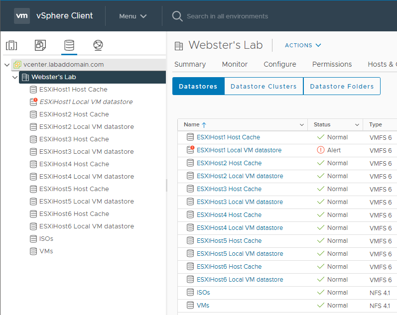
Figure 57 To verify the NFS ISO datastore, upload an ISO to the datastore.
Right-click the ISOs datastore and click Browse Files, as shown in Figure 58.
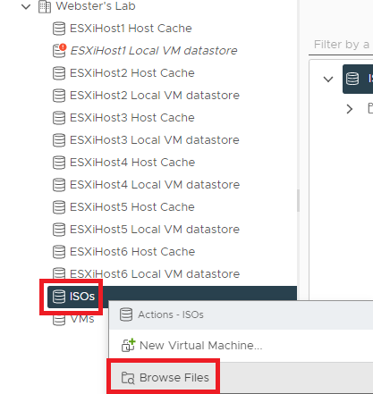
Figure 58 Click Upload Files as shown in Figure 59.
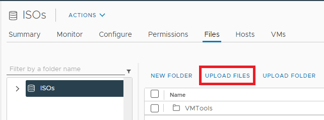
Figure 59 Browse to an ISO file, select it, and click Open, as shown in Figure 60. I am uploading a Windows Server 2019 ISO.
Note: You can download a 180-day evaluation copy of Windows Server 2019 (among other Microsoft products) from the Microsoft Evaluation Center.

Figure 60 The ISO file starts uploading to the ISOs datastore, as shown in Figure 61.

Figure 61 The ISOs show in the datastore once the ISO file upload is complete, as shown in Figures 62 and 63.

Figure 62 
Figure 63 Now that we have created shared datastores, we need to move the vCenter storage from the local datastore to the shared VMs datastore. Moving datastores eliminates the storage warning on the local datastore shown in Figure 64.

Figure 64 In the left pane, click VMs and Templates, right-click the vCenter VM, and click Migrate…, as shown in Figure 65.
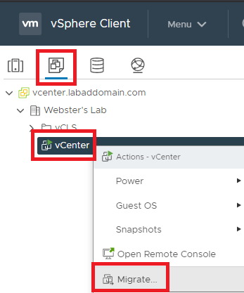
Figure 65 Select Change storage only and click Next, as shown in Figure 66.
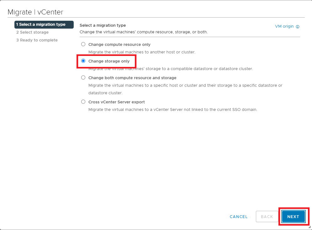
Figure 66 Select the datastore created for VM storage and click Next, as shown in Figure 67.
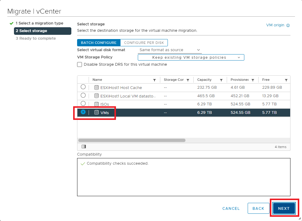
Figure 67 If all the information is correct, click Finish, as shown in Figure 68. If the information is not correct, click Back, correct the information, and then continue.
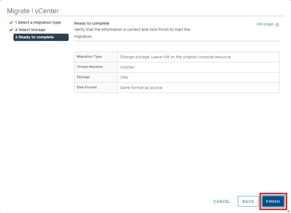
Figure 68 As shown in Figure 69, the storage migration starts.

Figure 69 Note: In my lab, the storage migration took just over one hour.


June 1, 2021
VMware